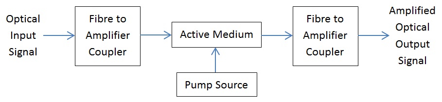
Optical Fiber AmplifiersExternal pump source supplies energy. This energy is absorbed by electrons in active medium. Population inversion is then created by the energised electrons. Photons then replicate in the active medium.
Doped Fiber Amplifiers
Doped glass is used in active medium block. The pump wavelength is chosen to match absorption wavelength of doped glass. Light from pump and optical signal propagate simultaneously through the active medium. Erbium Doped Fiber Amplifier (EDFA) Erbium doped fiber amplifier (EDFA) is the most common optical amplifier in use. Those amplifiers are made from silica glass. EDFAs have 40 dB gains and 100 mW output power, low noise and low coupling loss. They operate in 1530 nm – 1560 nm wavelength band. An EDFA contains 5-30 m Er-doped silica fiber, pump light source 50 – 100 mW, two optical isolators and optical filter. Isolators are used to supress oscillations caused by amplification of reflected power. Amplified Spontaneous Emission (ASE) feedback is thus eliminated. The filter is used to supress ASE noise in gain bandwidth. Both forward, backward and bidirectional pumping configurations can be applied. Forward Pumping 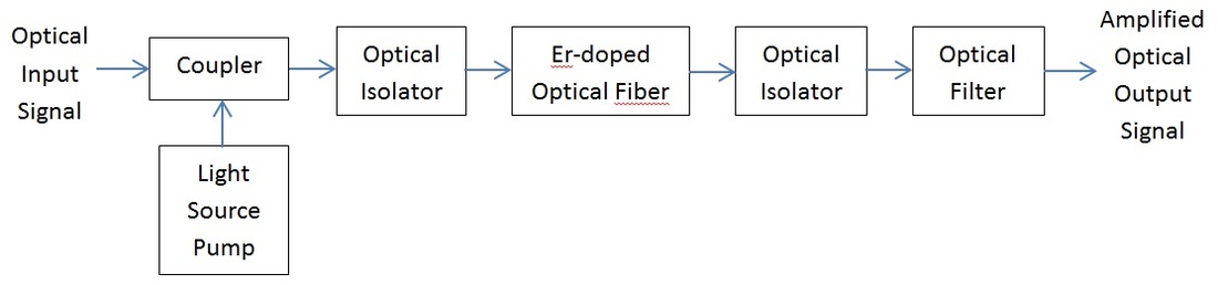
Backward Pumping 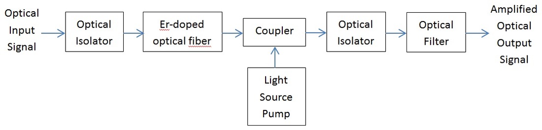
Gain The amplifier gain is equal to: 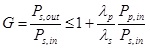
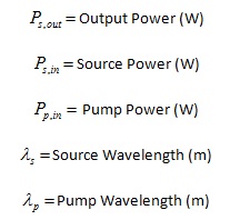
Where:
EDFA gain is influenced by:
- density of Er3+ ions, - density of signal photons, - density of pump photons, - interaction length (fibre length) Gain saturation happens if: - number of signal photons > number of excited Er ions, - run out of Er ions (occurs when gain is high), - run out of pump photons (usually occurs at far end of fibre). In gain saturation region the system gain falls below maximum level. The gain of EDFA is not flat across the spectrum. Gain equalisation filters are used to flatten the system response. Amplifier Noise Noise in optical amplifiers is mostly caused by amplified spontaneous emission (ASE). The noise spectral density of ASE noise equals to: 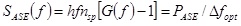
Where: h = Plank’s Constant (6.625*10^-34 Js)
G = Gain 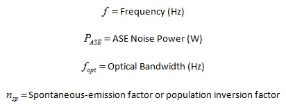
The noise figure is given by:
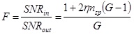
Where: SNR = Signal to Noise Ratio
G = System gain 
For high values of G:

Typical NF is 5 to 6 dB.
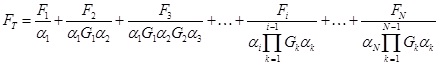
Cumulated noise in cascaded systems reduces the signal level. The ASE noise spectral density in cascades EDFA amplifier systems is: 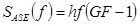
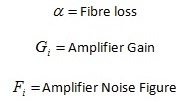
Where: G = Gain
F = Noise Figure h = Plank’s Constant (6.625*10^-34 Js) 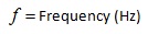
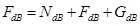
Total noise figure for cascaded amplifiers is:
Where: N = Number of Amplifiers
If all gains and noise figures are equal and fibre loss equals to fibre gain then:

The optical SNR at output of cascaded amplifiers approximately equals to:
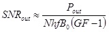
Where: N = Number of amplifiers
G = Gain F = Noise Figure h = Plank’s Constant (6.625*10^-34 Js) f = frequency (Hz) 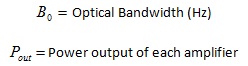
Raman Amplifiers Raman amplifiers use Stimulated Raman Scattering (SRS). SRS is a non-linear interaction between photons and high frequency molecular vibrations (phonons). Optical power is transferred from one wavelength to another wavelength by the energy of a phonon. Photons with smaller energy and longer wavelength stimulate the emission of cloned photons entering the fiber. A phonon is then excited by residual energy. Raman gain occurs when optical fiber is pumped at high power above 500 mW. Advantages of Raman amplifiers include: - ASE noise is less than in EDFAs - simple design - gain over a wide wavelength range. Multi-pump wavelengths and adjustment of pump powers is used. Distributed Raman Amplifiers (DRAs) amplify in transmission fiber. Discrete Raman Amplifiers pump power confined to short length of special fibre with enhanced Raman gain. Gain medium is dispersion compensating fiber. |
