RF Photonic LinksRF photonic systems are analogue electronic circuits that transmit microwave and millimeter-wave RF signals over optical fiber. Those systems are also referred to as Radio over Fiber and Fiber wireless systems.
Advantages of such systems include: - wide bandwidth, - low transmission loss, - small cable size and weight, - immunity from EMI and crosstalk. Applications include: - satellite systems, radio astronomy, - phased-array antennas, - broadband wireless access networks, - CATV systems, - distribution of wireless and TV broadcast signals in buildings, tunnels, subways, - distribution of radar signals on ships and airplanes, - defense – electronic warfare. Direct Modulation and External Modulation RF photonic link can work with direct modulation or external modulation. In direct modulation the modulating signal is multiplies the bias current supplied to the laser diode. In external modulation the laser diode signal is fed into external optical modulator that modulates the signal with applied RF voltage. External modulation has greater bandwidth and dynamic range. Distortion Non-linear properties of modulating systems cause distortion. Signal under distortion is given by: 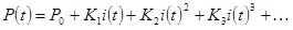
If:
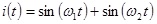
then:


The
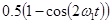
and
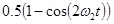
are the harmonic distortion terms.
The 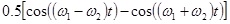
are the intermodulation distortion terms.
RF Photonic Link Parameters The following parameters are used to specify RF photonic link characteristics: - link gain - bandwidth - noise (laser diode, optical amplifier, photodiode, receiver amplifier) – shot noise, thermal noise - dynamic range - distortion Equivalent input noise that is used to specify RF photonic link performance is given by: EIN = Output Noise / Link Gain
EIN (dBm) = Output Noise (dBm) – Link Gain (dB) EIN is usually defined over 1 Hz bandwidth. Thus units are mW/Hz or dBm/Hz.
Another parameter is the noise figure: NF = 10 log (EIN/kT)
= 10 log EIN – 10 log kT Where: k is Boltzmann Constant = 1.3806488*10^-23 and T is temperature |
